In this post I will explain how to build, subdivide and texture an icosahedron. Look at the ending of the post for eye candy.
So I’ve been following the development of Notch’s new game, 0x10^c, which is looking really exciting. When I saw a screenshot(Can’t find it now) I was reminded of something I read about using icosahedrons to make planets in 3D with minimal distortion when mapping to a texture.
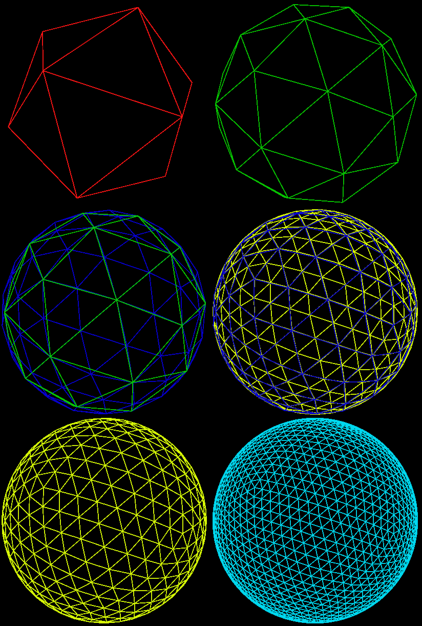
I find this way of attacking the problem of spheres fascinating. Basically you start off with a 20 sided die and split the faces by adding new vertices on a sphere encapsulating the icosahedrons, so in each iteration you get closer to a perfect sphere. You split the faces by adding a point in the middle of each edge in a triangle, you then construct four new triangles using these and the original vertices.
I found a very good article on how to do this, and I’m just gonna steal the recipe for building icosahedrons from that article. You can find the article here.
So to accomplish this I use an array list which contains a list of points to be added to a mesh.
The engine I use has the triangle list method of adding polygons set by default, which means I have to feed it 3 points every time I want to define one triangle, instead of defining every triangle based on points added by the last. So I built each triangle individually and ended up with a lot of redundant vertices when I wrote the code. This could probably be avoided by using another way of adding polygons.
I start by filling a fixed size array with the points needed to construct a icosahedron and add them to my list. To subdivide I run through each triangle, find the three middles of each edge and create 4 new triangles using the 3 original and 3 new points I have. I make sure to offset the vertices so that they end up on a hypothetical sphere. According to Wikipedia all the points from the center to a vertex on the icosahedron is defined by the golden ratio; (1+sqrt(5))/2 and 1, so the radius of the hypothetical sphere touching each vertex of the icosahedron, will be sqrt(((1+sqrt(5))/2)^2+1^2+0), since this will be the coordinates of each vertex in some order, the Cartesian coordinates can be seen here. So I will offset all vertices by sqrt(((1+sqrt(5))/2)^2+1) from the center.
Throughout my post I will refer to my main list of points as vertexList and assume that we have a 3-dimensional vector data structure; Vector3D, available with the attributes x, y and z. Also I’ll assume we have defined a float; size, to easily change the size of our icosahedron. Rounding errors will occur if this is too small!
Below is pseudo code, which I have no experience writing.
Building the initial icosahedron:(stolen from this article. )
method addFace(Vector3D v1, Vector3D v2, Vector3D v3)
	{
	//Add a triangle to our vertex list
	vertexList.add(v1);
	vertexList.add(v2);
	vertexList.add(v3);
	}

method buildIcosahedron()
	{
	//The golden ratio
	float t = (1 +sqrt(5))/ 2;

	//Define the points needed to build a icosahedron, stolen from article
	3DVector[] vecs = new 3DVector [12];
	vecs[0] = new 3DVector(-size, t*size, 0);
	vecs[1] = new 3DVector(size, t*size, 0);
	vecs[2] = new 3DVector(-size, -t*size, 0);
	vecs[3] = new 3DVector(size, -t*size, 0);

	vecs[4] = new 3DVector(0, -size, t*size);
	vecs[5] = new 3DVector(0, size, t*size);
	vecs[6] = new 3DVector(0, -size, -t*size);
	vecs[7] = new 3DVector(0, size, -t*size);

	vecs[8] = new 3DVector(t*size, 0, -size);
	vecs[9] = new 3DVector(t*size, 0, size);
	vecs[10] = new 3DVector(-t*size, 0, -size);
	vecs[11] = new 3DVector(-t*size, 0, size);

	// 5 faces around point 0
	addFace(vecs[0], vecs[11], vecs[5]);
	addFace(vecs[0], vecs[5], vecs[1]);
	addFace(vecs[0], vecs[1], vecs[7]);
	addFace(vecs[0], vecs[7], vecs[10]);
	addFace(vecs[0], vecs[10], vecs[11]);

	// 5 adjacent faces
	addFace(vecs[1], vecs[5], vecs[9]);
	addFace(vecs[5], vecs[11], vecs[4]);
	addFace(vecs[11], vecs[10], vecs[2]);
	addFace(vecs[10], vecs[7], vecs[6]);
	addFace(vecs[7], vecs[1], vecs[8]);

	// 5 faces around point 3
	addFace(vecs[3], vecs[9], vecs[4]);
	addFace(vecs[3], vecs[4], vecs[2]);
	addFace(vecs[3], vecs[2], vecs[6]);
	addFace(vecs[3], vecs[6], vecs[8]);
	addFace(vecs[3], vecs[8], vecs[9]);

	// 5 adjacent faces
	addFace(vecs[4], vecs[9], vecs[5]);
	addFace(vecs[2], vecs[4], vecs[11]);
	addFace(vecs[6], vecs[2], vecs[10]);
	addFace(vecs[8], vecs[6], vecs[7]);
	addFace(vecs[9], vecs[8], vecs[1]);
	}
Now we have our icosahedron, and we just need to subdivide it’s faces. I will define a method which can be applied to the icosahedron any number of times depending on the level of detail needed. First we will define a method to find the middle of a line segment between two points:
function getMiddle(3DVector v1, 3DVector v2)
	{
	//The golden ratio
	float t = (1 + sqrt(5)) / 2;

	3DVector temporaryVector = new 3DVector;

	//Calculate the middle
	temporaryVector = (v2-v1)*0.5+v1;

	//Offset point
	temporaryVector.normalize();
	temporaryVector *=sqrt(t*t+1)*size;

	return temporaryVector;
	}
And now we can subdivide:
method subdivideIcosahedron()
	{
	float t = (1 +sqrt(5))/ 2;
	List newVertices = new List();

	3DVector newVector1;
	3DVector newVector2;
	3DVector newVector3;
	for (int i = 0; i < vertices.Count; i += 3)
		{
		//Find the middle points
		newVector1 = getMiddle(vertexList[i], vertexList[i + 1]);
		newVector2 = getMiddle(vertexList[i+1], vertexList[i + 2]);
		newVector3 = getMiddle(vertexList[i+2], vertexList[i]);

		//Add the new faces
		newVertices.Add(newVector3);
		newVertices.Add(vertexList[i]);
		newVertices.Add(newVector1);

		newVertices.Add(newVector1);
		newVertices.Add(vertexList[i + 1]);
		newVertices.Add(newVector2);

		newVertices.Add(newVector2);
		newVertices.Add(vertexList[i + 2]);
		newVertices.Add(newVector3);

		newVertices.Add(newVector1);
		newVertices.Add(newVector2);
		newVertices.Add(newVector3);
		}
	//Replace old points with new
	vertices = newVertices;
	}
And now we just need to convert it to a mesh:
method meshFromVertexList(TVMesh mesh)
	{
	mesh.setPrimitiveType(TRIANGLE_LIST)
	foreach (3DVector vertex in VertexList)
		{
		mesh.AddVertex(vertex);
		}
	}
In this last piece of pseudo code I am not considering normals or UV-mapping. Partly because the engine has a method, computeNormals() and partly because I haven’t completely figured out the UV-mapping technique yet.
The application is written in C# using VS2010 express, .NET 3.5 and TrueVision3D. I usually use this setup for testing out ideas and learning since it’s an extremely easy setup. I’m currently learning OpenGL with C++ using some really great tutorials located here.
UV MAPS!
I just figured out how to make an UV-map for our icosahedron, it’s so obvious!
Basically, you just do it exactly the same way we built the icosahedron, but this time in 2D. We start off building a regular 20 sided icosahedron and then we subdivide EXACTLY the same way we subdivided the icosahedron, except we don’t offset the points.
I’ll assume we have an array list called UV, which contains 2D vectors and is used to map the vertices of the vertexList to a texture. The addUVFace method is the same as addFace, but this time we add three 2D vectors to the UV list. First we build the UV map:
method buildUVMap()
	{
	//The number of points horizontally
	float w = 5.5f;
	//The number of points vertically
	float h = 3f;

	//An array of the points needed to build the basic UV map
	2DVector[] UVPoints = new 2DVector[22];

	UVPoints[0] = new 2DVector(0.5f / w, 0);
	UVPoints[1] = new 2DVector(1.5f / w, 0);
	UVPoints[2] = new 2DVector(2.5f / w, 0);
	UVPoints[3] = new 2DVector(3.5f / w, 0);
	UVPoints[4] = new 2DVector(4.5f / w, 0);

	UVPoints[5] = new 2DVector(0, 1 / h);
	UVPoints[6] = new 2DVector(1f / w, 1 / h);
	UVPoints[7] = new 2DVector(2f / w, 1 / h);
	UVPoints[8] = new 2DVector(3f / w, 1 / h);
	UVPoints[9] = new 2DVector(4f / w, 1 / h);
	UVPoints[10] = new 2DVector(5f / w, 1 / h);

	UVPoints[11] = new 2DVector(0.5f / w, 2 / h);
	UVPoints[12] = new 2DVector(1.5f / w, 2 / h);
	UVPoints[13] = new 2DVector(2.5f / w, 2 / h);
	UVPoints[14] = new 2DVector(3.5f / w, 2 / h);
	UVPoints[15] = new 2DVector(4.5f / w, 2 / h);
	UVPoints[16] = new 2DVector(1, 2 / h);

	UVPoints[17] = new 2DVector(1f / w, 1);
	UVPoints[18] = new 2DVector(2f / w, 1);
	UVPoints[19] = new 2DVector(3f / w, 1);
	UVPoints[20] = new 2DVector(4f / w, 1);
	UVPoints[21] = new 2DVector(5f / w, 1);

	//first row
	addUVFace(UVPoints[0], UVPoints[5], UVPoints[6]);
	addUVFace(UVPoints[1], UVPoints[6], UVPoints[7]);
	addUVFace(UVPoints[2], UVPoints[7], UVPoints[8]);
	addUVFace(UVPoints[3], UVPoints[8], UVPoints[9]);
	addUVFace(UVPoints[4], UVPoints[9], UVPoints[10]);

	//second row
	addUVFace(UVPoints[7], UVPoints[6], UVPoints[12]);
	addUVFace(UVPoints[6], UVPoints[5], UVPoints[11]);
	addUVFace(UVPoints[10], UVPoints[9], UVPoints[15]);
	addUVFace(UVPoints[9], UVPoints[8], UVPoints[14]);
	addUVFace(UVPoints[8], UVPoints[7], UVPoints[13]);

	//fourth row
	addUVFace(UVPoints[17], UVPoints[12], UVPoints[11]);
	addUVFace(UVPoints[21], UVPoints[16], UVPoints[15]);
	addUVFace(UVPoints[20], UVPoints[15], UVPoints[14]);
	addUVFace(UVPoints[19], UVPoints[14], UVPoints[13]);
	addUVFace(UVPoints[18], UVPoints[13], UVPoints[12]);

	//third row
	addUVFace(UVPoints[11], UVPoints[12], UVPoints[6]);
	addUVFace(UVPoints[15], UVPoints[16], UVPoints[10]);
	addUVFace(UVPoints[14], UVPoints[15], UVPoints[9]);
	addUVFace(UVPoints[13], UVPoints[14], UVPoints[8]);
	addUVFace(UVPoints[12], UVPoints[13], UVPoints[7]);
	}
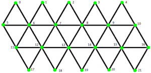
Figuring out which point mapped to which vertex was a pain, so I made this figure to help me out. But the faces of the icosahedron was in a bit of a random order, since I just copied the recipe.
To subdivide we first define a way to find the middle point between two points. This is the same as getMiddle function, but in 2D. So we just make an overloaded version of the getMiddle function, which takes two 2D vectors:
function getMiddle(2DVector v1, 2DVector v2)
	{
	2DVector temporaryVector = new 2DVector;

	//Calculate the middle
	temporaryVector = (v2-v1)*0.5+v1;

	return temporaryVector;
	}
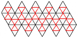
Now we subdivide, EXACTLY the same way as before. As you can see in this figure, each face gets subdivided in to four new faces, the overall structure of the UV map stays intact, so the same texture will still work on subdivided icosahedrons.
method subdivideUVMap()
	{
	List newUV = new List();

	2DVector newVector1;
	2DVector newVector2;
	2DVector newVector3;
	for (int i = 0; i < vertices.Count; i += 3)
		{
		//Find the middle points
		newVector1 = getMiddle(UV[i], UV[i + 1]);
		newVector2 = getMiddle(UV[i+1], UV[i + 2]);
		newVector3 = getMiddle(UV[i+2], UV[i]);

		//Add the new faces
		newUV.Add(newVector3);
		newUV.Add(UV[i]);
		newUV.Add(newVector1);

		newUV.Add(newVector1);
		newUV.Add(UV[i + 1]);
		newUV.Add(newVector2);

		newUV.Add(newVector2);
		newUV.Add(UV[i + 2]);
		newUV.Add(newVector3);

		newUV.Add(newVector1);
		newUV.Add(newVector2);
		newUV.Add(newVector3);
		}
	//Replace old points with new
	UV = newUV;
	}
Then we just call buildUVMap() in the buildIcosahedron method, subdivideUVMap() in the subdivideIcosahedron method and add the UV coordinates when building the mesh.
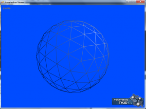
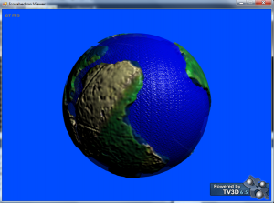
Here is a picture of an icosahedron with 20480 faces and an Earth texture. Sadly, the map is reversed and I can’t be arsed to fix it. You’ll see Denmark, where I live, in the middle of the screenshot.
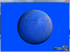
Here’s a wireframe version:
As you can see, the texture doesn’t align completely with the UV map. But I’m just gonna blame the texture here. Heheh.
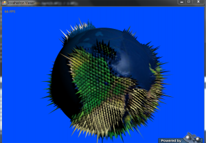
Failed attempt at height mapping:
I accidentally offset the points by a height map BEFORE subdividing the mesh, which resulted in only 1/4th of the vertices being height mapped.
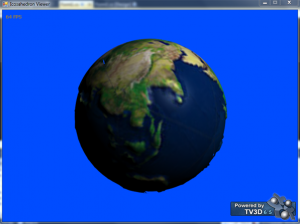
Successful attempt at height mapping:
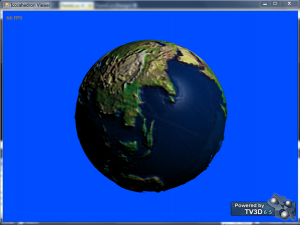
Combined with normal map:
Added water mesh:
I would hand out the source code, but I’ve lost it. It shouldn’t be too hard to rewrite the pseudocode to your language of choice though, since it is pretty explicit.

Pingback: Procedurally generated tree(With source) | CoreDumping
Hey there, nice roundup. I’d been following the same route as you (Wikipedia icosahedron cartesian co-ords and catch22) before I saw your page.
Something I’ve noticed with yours and catch22s implementation is with the midpoint sphere offset correction. Catch22 was going the trig route (Mathf.Sqrt(v3.x * v3.x + v3.y * v3.y + v3.z * v3.z) = 1.902133 and your route (sqrt(t*t+1)*size) came to the same result (stripping out size though)…. the problem is that multiplying the midpoints by that value is insanely adjusting the mesh, especially since the multiplier needs to be just above 1 (1 equalling no offset adjustment). I realised that the multiplier needed to be divided by the golden ratio, so: being 1.9021130251472 / 1.6180339887499 = 1.17557049998485, which is much more like the results I was after.
Anyway, results are king and your original code did the trick for you, I’ve only used this offset with the first subdivision because I’ve got to class and function up my working code so fingers crossed it’s allright. Cheers.
Hey, thanks for not being spam!
I never actually looked at catch 22’s code other than the initial vertex construction, so I never knew he did it differently. But I remember being unsure about the math here and rewriting the code a bit after this write up, so you’re probably right about your method being better, I don’t have the source anymore, so I can’t check if I came to the same conclusion.
Good luck with your class, I’m sure it’ll be alright 🙂
Cheers for that, another non spam comment coming through 🙂
Well my multiplication worked perfectly for the 1st subdiv, but the 2nd subdiv wasn’t behaving at all with it cumulatively getting worse on further iterations, so I just rewrote it so that the midpoint was worked out without the offset, then I normalized it and multiplied it by the magnitude (or length to origin) of the first vector so I know it’s a perfect sphere! Works a charm.
Hmm. Sounds like you’re offsetting all the vertices each time you subdivide. In my code I only offset the vertices being added, since the existing vertices are already on a sphere. In any case, I never had a problem with the icosahedron getting progressively worse.
I was only offsetting the newly created midpoints, but with the second subdivision I was getting different results with a variance of 0.1 which cumulatively got worse on further iterations. Rederiving from the sphere radius was what I wanted to do before I used the offset method because it was a guaranteed way of knowing it was of correct length, and now my renders in Unity are perfect!
As long as you’re normalizing the new vertices, logically there shouldn’t be any problems. I’ll try it myself in unity later to see if I can make sense of it.
Wow, I was working on procedurally generating a sphere for a couple weeks now and ran across catch 22’s stuff. Did a little reworking to get it to work and then had no clue what I was going to do about the UV’s. Put in something temp and the material/texture was all distorted and figured I would need to do the same exact thing to the UV’s with the subdivision. Your pseudo code just jumped my starting position ahead.
That’s great to hear. I thought about it a lot and came up with a lot of broken ideas, before I figured out what is seemingly quite obvious.
temporaryVector = (v2-v1)*0.5+v1 sooo…this line of code brings up a nice error…which does make sense. Can’t convert a Vector2 to an int which is the result of the equation there. What’s the best way to go about that? I’ve changed a few things around to be put into a List and I went to create the getMiddle portion of the code for the UV and it through that up. Now I’m trying to figure out how to re-code it to work with my code. This version does differ some from catch22’s code in which the getmiddlepoint takes in two ints, a list vector3, a dictionary, and radius. I figured since mapping out the UV’s is pretty much the same thing I worked on doing that but I can’t figure out how to wrap my brain around getting it to work with Vector2 UV coordinates. I guess I could have chosen something easier to do as my first coding experience (I have very very little programming experience) but it’s easier for me to learn when diving head first into something like this.
When are you converting to an int? UV coordinates consist of real numbers between 0-1. That line of code deals with real vectors and a real number, no integers.
So assuming vectors have the usual x and y variables, temporaryVector = (v2-v1)*0.5+v1 amounts to:
temporaryVector.x = (v2.x-v1.x)*0.5+v1.x
temporaryVector.y = (v2.y-v1.y)*0.5+v1.y
I’ve overridden the * operator for vectors and vectors, and vectors and doubles to work the way you’d expect when working with linear algebra.
I should note I haven’t seen catch22’s getmiddlepoint function, but the logic behind is pretty basic: You find a vector between two vectors by subtracting them(v2-v1), you get the middle point by dividing it(*0.5) and you offset by the first vector(+v1), now you’ll be halfway between v1 and v2. It shouldn’t matter what dimension you’re in.
Okay, I just checked out catch22’s getmiddle function. His is optimized to cache the middle points, so it returns an int, because it returns the index in an array where the middle point is, and if it doesn’t exist he creates it in the same way I do. It might be confusing since he has written (v1+v2)/2 but a little rewriting will tell you that (v1+v2)/2=(v1-v2)*0.5+v1, so mine is not optimized at all. He also explicitly calculates it for each coordinate in the code, whereas I’ve used operator overloads so I can just multiply vectors directly in the code, without caring about individual coordinates.
I guess I should have checked out to see if there was a reply earlier. I’m currently stuck on generating the UV’s to the icosphere, mostly because I get that ugly pole that goes from seam to seam.
When retrofitting the code above to work with the code from catch22’s page I get the error that mesh.uv doesn’t equal mesh.vertices. Maybe I’m just missing something here. I’m working in C# but I don’t think that makes a real difference.
I can see part of my problem. I build the vertice list and a face/indice list. Then I subdivide the face which only creates 3 more vertices. This is because the faces list is used to build the triangles for the mesh. I duplicated the process for creating UV’s which made the same amount of UV’s as there was triangle points. Hopefully when I figure this whole mess out I’ll be lucky to not have a pole to pole seam which has been present in all the other things I’ve tried.
I want to know how one can make the correspondence between the texture and the faces of the icosahedron in the different levels of subdivision.
You have to calculate the UV coordinates after the subdivision. I divided the sphere before applying the mesh. Getting it all lined up after applying the mesh is actually easier than I initially though. I currently just finished up trying to chunk out my sphere and subdividing the chunks but still keeping the texture mostly lined up. I basically subdivided the UV’s within the same function of the vertices because all you are really doing with the UV’s is something like
newUV1 = new Vector2((olduv1.x + olduv2.x) / 2f, (olduv1.y + olduv2.y) / 2f);
I know it’s probably not the most efficient as I still have a small seam that goes from pole to pole but it keeps the texture applied properly and you only notice the change in the mesh briefly. Depending on the distance from the player to the chunk.
My main problem now is trying to figure out how to do a heightmap from texture onto the sphere using perlin noise…or improved perlin noise I should say. Anyone know of a good tutorial or example code of that? Do I need to put the noise function into the shader or is there a way to do it in the script?
Hello,
I have an icosahedral structure (ico) defined in Matlab as follows:
the coordinates of the vertices are as follows:
ico.uv = [
% 0 0 -1;
% -0.2764 -0.8507 -0.4472;
% 0.7236 -0.5257 -0.4472;
% 0.7236 0.5257 -0.4472;
% -0.2764 0.8507 -0.4472;
% -0.8944 0 -0.4472;
% 0.2764 -0.8507 0.4472;
% 0.8944 0 0.4472;
% 0.2764 0.8507 0.4472;
% -0.7236 0.5257 0.4472;
% -0.7236 -0.5257 0.4472;
% 0 0 1;
% ]
and the faces are defined as follows:
ico.f = [
1 3 2 ;
1 4 3 ;
1 5 4 ;
1 6 5 ;
1 2 6;
2 3 7 ;
3 4 8 ;
4 5 9 ;
5 6 10 ;
6 2 11;
7 3 8 ;
8 4 9 ;
9 5 10 ;
10 6 11 ;
11 2 7;
7 8 12 ;
8 9 12 ;
9 10 12 ;
10 11 12 ;
11 7 12];
I tried to apply this method for an icosahedron with texture icosaèdre.unfortunately I could not do that, I need someone who can help me to make the texture of an image on the faces of the icosahedron.
thank you
Noureddine
So, I came across another issue with subdividing the UV’s. After they get subdivided a certain amount it completely screws up my UV’s to where there are some pole pinching artifacts everywhere. If I reduce the subdivision count by 1 there are no issues. Also need to note that I had to put in a shader because I ran across and extremely ugly seam going from pole to pole and I didn’t want to duplicate vertices. I think a majority of the problem has to do with my shader and possibly problems with precision? Here’s the shader I came up with. If anyone has any ideas what I could do to either the shader…or even and more preferably through script let me know.
Shader "Custom/isoshader" {Properties {
decal ("Base (RGB)", 2D) = "black" {}
decBump ("Bumpmap (RGB)", 2D) = "bump" {}
}
SubShader {
Pass {
Fog { Mode Off }
Tags { "RenderType"="Opaque" }
LOD 200
CGPROGRAM
#pragma vertex vert
#pragma fragment frag
#define PI 3.141592653589793238462643383279
sampler2D decal;
sampler2D decBump;
struct appdata {
float4 vertex : POSITION;
float4 color : COLOR;
float4 texcoord : TEXCOORD0;
};
struct v2f {
float4 pos : SV_POSITION;
float4 tex : TEXCOORD0;
float4 col : COLOR0;
float3 pass_xy_position : TEXCOORD1;
};
v2f vert(appdata v){
v2f o;
o.pos = mul(UNITY_MATRIX_MVP, v.vertex);
o.pass_xy_position = v.vertex.xyz;
o.tex = v.texcoord;
o.col = v.color;
return o;
}
float4 frag(v2f i) : COLOR {
float3 tc = i.tex;
tc.x = (PI + atan2(i.pass_xy_position.x, i.pass_xy_position.z)) / (2 * PI);
float4 color = tex2D(decal, tc);
return color;
}
ENDCG
}
}
}